You’ll note that the map is missing. I’ve been experimenting so that it would become interactive. Unfortunately Google now charges for use of an interactive map although the first $200 worth is free.
I’m looking into it but reluctant to put my credit card to the test. I’m looking at alternatives but as we all know the Google Maps is the best.
Hang in there I’ll see what I can do over the next few weeks. I’m a beginner at WordPress.
The Heywood Rally will require us on Saturday 27th April only. It’s an early start at 7:00AM. Peter VK5BE is managing this event.
Communication will be via the Portable repeater which operates on the Willalooka frequency 147.350 (your receiver) and 147.950 (your transmitter). Peter and Colin will have checked out communications the week before (20/4/19) and it is expected that the repeater will cover the required area.
The repeater has a 1 second tail but no beep. It has a 10 minute timeout.
The repeater is running on two antennas – both folded dipoles with the receiver on top so it’s expected that a handheld should get in okay.
The Generations in Jazz event is on from 3,4,5 May. Andrew VK5KET is managing this event. Volunteer times to be advised.
The portable repeater is being placed approximately 1km from the Generations in Jazz site and will provide rock crushing signals to the area. Again the frequencies are 147.350 (listen) and 147.950 (transmit).
On Sunday Tom VK5NFT, Alan VK5ZLT and I (VK5DJ) travelled to the Willalooka site. An 8:15AM departure was a bit much for DJ but he managed it. Tom drove and we arrived on site at 10:20AM. We were pleased to have a police escort for a little while – most appropriate for such an important visit.
The aim was to find the cause of the mixing product from 3WV, identify the changing signal strength on the Willalooka transmission and fix the noise that occasionally opens the Willalooka mute and propagates around the whole network. Not a bad list.
What did we find? Not much.
With the aid of his antenna analyser Tom checked the two repeater antennas, viz. the main one near the top of the tower and a temporary test antenna lower down. Both tested with an SWR of 1.2 at the TX frequency but about a MHz higher the SWR was 1:1. So the SWR favoured the RX rather than the TX. The sweep was broad so we decided that the antennas were near enough for government work.
One possible problem found was the antenna coax going into the cavities. It seemed to rotate within the plug. Further examination revealed threads of outer that may have been shorting out to the inner. Tom re-terminated the coax and tightened the nut, we felt much better about that. We checked all plugs for firm connections. Next John got out his DSA815 spectrum analyser/tracking generator and used it to sweep the cavities. The passband and notches checked out and when the cavities were reconnected to the TX and RX no receiver de-sense was evident. VK5ZAI at Kingston reported favourably on access.
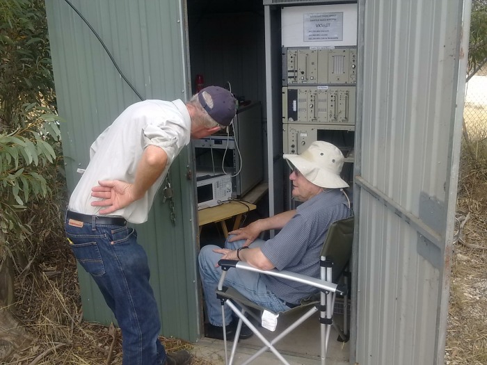
Alan VK5ZLT and John VK5DJ discuss the cavity display
The repeater was re-assembled, connectors tightened and put on the original antenna. The mute was tightened a whisker to avoid noise opening the mute. It may be a little tight and cause chopping but better than noise holding up the network. We left the site about 1:30PM.
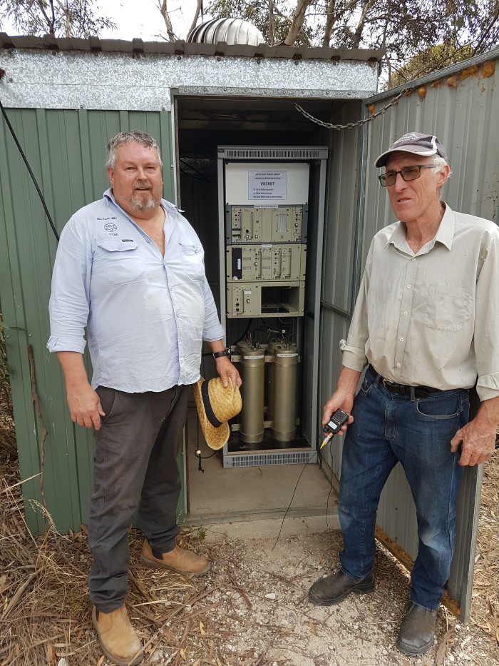
Tom VK5NFT and Alan VK5ZLT before closing up for the day
We thank Tony VK5ZAI for providing test signals during the day’s exercise. It makes a big difference having a distant station.
How to Tune a Band Pass Cavity using a DSA 815 Spectrum Analyzer
The above Youtube clip provided by Tom doesn’t apply to our cavities as ours are passband with a notch. Ours are more critical to tune, however it does give an idea about what is necessary for passband only.
Our cavities have a passband for the RX and TX but they also have a notch in their response 600kHz away. TX cavities have a notch on the RX frequency to remove transmitter noise, while receiver cavities have a notch in their response to remove the carrier. The video does show how to adjust the impedance match of the links and I haven’t done this in the past just adjusted the links for least loss. It might mean the same but in the short term I’ll practice this before next having to do this at a site. Never too young to learn.
At the meeting on 1/2/19 I described how we might use the club’s antenna analyser to best effect.
An important part of using the analyser is to understand the idea of standing waves.
I found this good illustration on youtube:
Hang in there, it’s a little slow moving but the illustration towards the end gives a really good visualisation of standing waves when there is a correct load and an open circuit.
How to tell if your SWR bridge is misleading you. Have on hand an extension length of coax. It should be a ¼ wavelength long for the band you are experimenting with. After measuring your SWR, insert the extra length in the line – this moves your testing point 1/4 wave along the coax to a different point on the standing wave.
Here are some useful lengths:
6M band use a length of 1 metre, 2M band use 340 mm,70cm band use 13cm.
It’s not too critical. Now if your two SWR readings are similar (e.g. 1.2 and 1.3 then you probably don’t have a big problem but 1.2 and 2 would be unacceptable and require more investigation.
To actually calculate the length of the 1/4 wave section the formula is: 75*0.67/freq in MHz and the answer is in metres.
e.g. for 2M it’s 75*0.67/144.0 = 0.348 metres
I’ve used 0.67 as the velocity factor, this is true for many coax cables. Heliax is more likely to be 0.8.
Recently a number of South East Radio Group members have been tracking weather balloons here in South East South Australia.
A balloon is released automatically from the Mount Gambier Airport each Monday and Thursday morning at 10.45 a.m. local time and if some unusual weather conditions are expected, at any time.
We watch the predicted flight path on Hab Hub Predictor and then track the actual flight path on Hab Hub Tracker. Sometimes the two plots agree and others not very well.
The prediction for yesterdays balloon originally had it landing somewhere near Hamilton but this was revised to a spot just East of Strathdownie in Victoria.
Charles, VK5HD rang me at about 11 a.m. and asked if I was going to chase it or if I might be interested in doing so. As it was not going to be very far from the Mount I suggested that I ring Tom, VK5EE, and invite him as well. Charles agreed and Tom and I met up with him at his home in Mt. Gambier at 1 p.m. and off we went.
After crossing the border on the way to Casterton we turned right onto West Strathdownie Road and then turned right onto McGrath’s Road. We travelled along McGrath’s Road for a short time until our GPS indicated that we were getting close to the landing area.
Charles had his hand held on and tuned to 401.500 Mhz. and right on cue we started to hear the signals from the Sonde. It had landed pretty much exactly where the tracker had placed it. We turn off McGraths road and drove a few hundred metres up along the Western edge of a stand of pine trees and parked.
After climbing over the fence into the paddock Charles thought he could see the Sonde but it turned out to be the wool from a sheep carcass.
Col, VK5HCF thought that he saw it just a bit to the North and so we changed direction and carried on walking. Bingo. There was the Balloon, (in tatters of course), and the parachute. Col traced the flimsy line from the tangled mess of the Balloon back to the actual sonde. The line was surprisingly long, maybe 30 metres or so.
All good. Charles coiled the whole mess up and we carried it all back to the car pretty happy with such an easy recovery.
We were only away for about an hour or so which meant minimal disruption to our day.
The Club is once again connected to the internet. The I.R.L.P. and the remote station are all working properly and there has been a dramatic increase in upload / download speeds.
John, VK5DJ, has updated the Remote Access details on the relevant page of this site.
A huge “Thank you” to Brett of T.D.R.S. for:-
1. Supplying us with excellent internet at no cost. 2. For maintaining the system – also free of charge. 3. Updating the system to the N.B.N.
If you are looking for a new provider – look no further than T.D.R.S. who are, of course, locals.
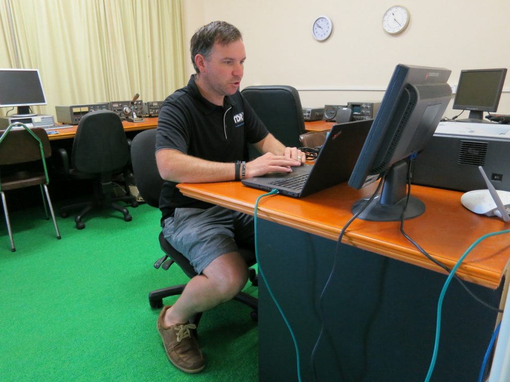
Brett, hard at work, setting up our Clubroom’s for the N.B.N.
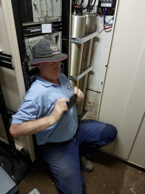
Peter VK5BE finding the best spot to get a good photo of the whole cabinet
Peter VK5BE and John VK5DJ visited the VK5RMG site on Monday 7th January 2019. This followed a visit the previous day to install the new link chassis and filters.
The link receiver from Naracoorte was program damaged (it lost its default frequency). A quick burst with the programmer at home and all is sweet. The whole system is now working with a somewhat faster ID. That’ll test your CW skills.
WSJTX is now in a new version 2.0 and is no longer compatible with previous versions.
If you are having trouble decoding signals it may be that you don’t have the latest version. Update and it’s like magic, back to copying people and working them again.
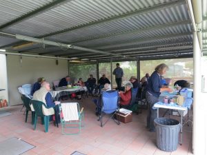
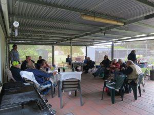
This year our Club end of year BBQ was held at the home of Greg, (VK5ZGY), and Gabi at Worrolong. This proved to be a very lucky move as the weather was cold, wet and windy and their back patio provided shelter from both the wind and the rain.
Attendance was possibly down a little on last years event but the quality of those attending was excellent.
President Peter, VK5BE, formally thanked Greg and Gabi for allowing us to hold the BBQ at their home and he also thanked those present for coming along. He then wished everyone all the very best for Christmas and the New Year.
Much chatter was evident and some lucky members got a tour of Greg and Gabis very environmentally conscious garden and all the electronic and bio friendly wizardry that is associated with it.
There was also a bit of “Show and Tell” with Chris, VK5MC, parading his recently acquired Elad S.D.R. radio and Tom, VK5EE showed off his Solar Panel.
On Monday 5th. November The Club held a working Bee at the Clubrooms.
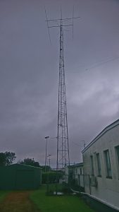
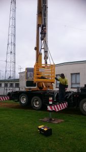
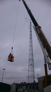
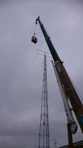
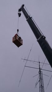
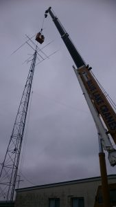
Colin, VK5DK, had made arrangements for Blue Lake Cranes to come along and help us to swap the old and dilapidated 2 metre antenna for the brand new one built by Ian, VK3DNQ and modified by Trevor, VK5NC.
With plenty of willing helpers the exercise went well, (after a few minor hiccups) and the new antenna is now ready to use.
Here are a few shots taken of the event by Club Treasurer Andrew, VK5VKC.