On Sunday Tom VK5NFT, Alan VK5ZLT and I (VK5DJ) travelled to the Willalooka site. An 8:15AM departure was a bit much for DJ but he managed it. Tom drove and we arrived on site at 10:20AM. We were pleased to have a police escort for a little while – most appropriate for such an important visit.
The aim was to find the cause of the mixing product from 3WV, identify the changing signal strength on the Willalooka transmission and fix the noise that occasionally opens the Willalooka mute and propagates around the whole network. Not a bad list.
What did we find? Not much.
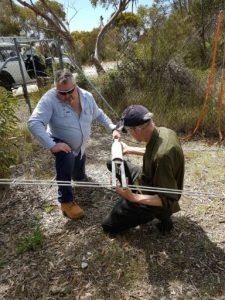
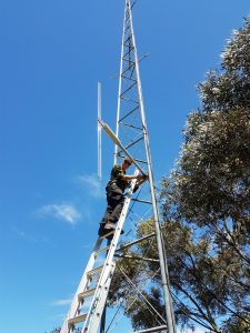
With the aid of his antenna analyser Tom checked the two repeater antennas, viz. the main one near the top of the tower and a temporary test antenna lower down. Both tested with an SWR of 1.2 at the TX frequency but about a MHz higher the SWR was 1:1. So the SWR favoured the RX rather than the TX. The sweep was broad so we decided that the antennas were near enough for government work.
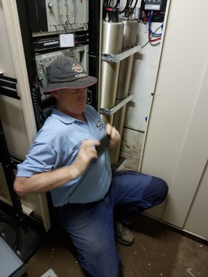
One possible problem found was the antenna coax going into the cavities. It seemed to rotate within the plug. Further examination revealed threads of outer that may have been shorting out to the inner. Tom re-terminated the coax and tightened the nut, we felt much better about that. We checked all plugs for firm connections. Next John got out his DSA815 spectrum analyser/tracking generator and used it to sweep the cavities. The passband and notches checked out and when the cavities were reconnected to the TX and RX no receiver de-sense was evident. VK5ZAI at Kingston reported favourably on access.
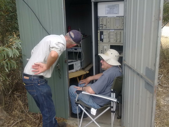
The repeater was re-assembled, connectors tightened and put on the original antenna. The mute was tightened a whisker to avoid noise opening the mute. It may be a little tight and cause chopping but better than noise holding up the network. We left the site about 1:30PM.
We thank Tony VK5ZAI for providing test signals during the day’s exercise. It makes a big difference having a distant station.
The above Youtube clip provided by Tom doesn’t apply to our cavities as ours are passband with a notch. Ours are more critical to tune, however it does give an idea about what is necessary for passband only.
Our cavities have a passband for the RX and TX but they also have a notch in their response 600kHz away. TX cavities have a notch on the RX frequency to remove transmitter noise, while receiver cavities have a notch in their response to remove the carrier. The video does show how to adjust the impedance match of the links and I haven’t done this in the past just adjusted the links for least loss. It might mean the same but in the short term I’ll practice this before next having to do this at a site. Never too young to learn.